Fiber Optic Cable
basic knowledge
What is Fiber Optic Cable ?
Ⅱ-24J1063-014
Optical Fiber
An optical fiber is a cylindrical optical waveguide that transmits light over a distance. It has better communication performances than copper wire.
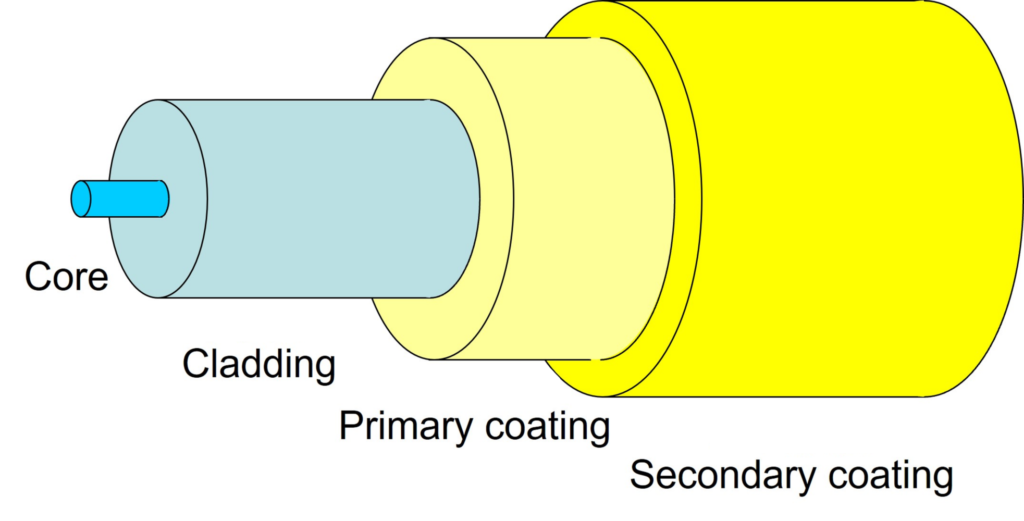
Figure (1) is a typical structure of a commonly used silica glass optical fiber used in telecommunication. There is a part called the core in the center that transmits light, and on the outside there is a part called the cladding that prevents light from leaking outside. Germanium is doped in the core to make it have a higher refractive index than the cladding. This allows light to be confined inside the core. There are also fiber types that have fluorine doped to lower the refractive index of the cladding. On the outside of the cladding is a primary coating of soft material, and outside of that is a secondary coating of hard material. The two-layered coating protects the quartz part from external damage while maintaining its flexibility. Compared to copper wires, optical fibers are: (1) smaller in diameter and lighter in weight; (2) less susceptible to electrical noise and interference; (3) transmission loss is extremely low, allowing long-distance transmission; and (4) light pulse width is extremely narrow. Since it can be switched on and off at high speed, high-speed, large-capacity communication is possible.
Types of Optical Fibers
Depending on application, optical fibers are divided into two; for communication use and for special use.
For Communications
For communications, there are single mode optical fiber (SMF) and multimode optical fiber (MMF). SMF is suitable for long-distance, high-capacity transmission because it has low loss and the shape of the optical pulse is not easily distorted. On the other hand, although MMF has the disadvantage that the pulse shape is easily distorted due to the differing speeds of the modes, it has the advantage that the light source and equipment used can be designed at low cost due to its large core diameter, and it can be used for short-distance transmission (LAN cables, etc.). SMF also offers low attenuation with improved bend loss characteristics. Previously, fibers with an outer diameter of 250 μm were the mainstream, but due to the demand for smaller cable diameters, fibers with an outer diameter of 200 μm are now becoming more popular. There are variety of optical fibers such as non-doped silica cores, photonic crystals, and multi-core optical fibers (MCF) that have multiple cores in one optical fiber. Fiber optic cables using MCF have the advantage of being smaller in diameter than normal SMF.
For specialty applications
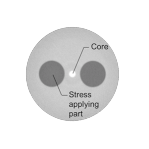
Special applications include sensors, image fibers, etc. Sensor applications include fiber optic gyros and polarization maintaining fibers (PMF) used for strain and temperature measurements. Figure (2) is a cross-sectional view of polarization maintaining fiber (PANDA fiber). Birefringence is induced by applying stress to the core using stress-applying materials placed on both sides of the core. The wavelength range of light used for communications is limited to a narrow range, but the wavelength range of light used for special purposes is extremely wide, so there are PANDA fibers that support each wavelength.
Fiber Optic Cables
A fiber optic cable is made by bundling of optical fibers (optical fiber cores, optical fiber cords) and applying a protective coating called a sheath. Fiber optic cables are used for communication purposes and are essential for realizing the information and communication infrastructure that supports the evolution of AI and IoT (Internet of Things).
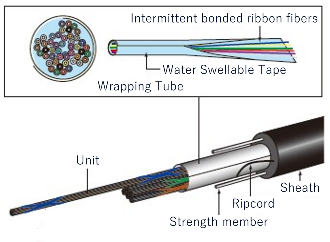
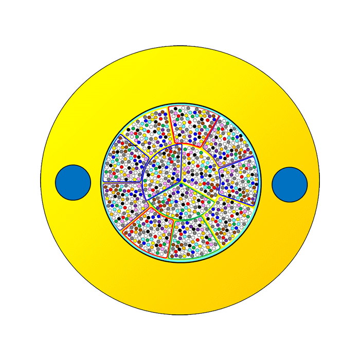
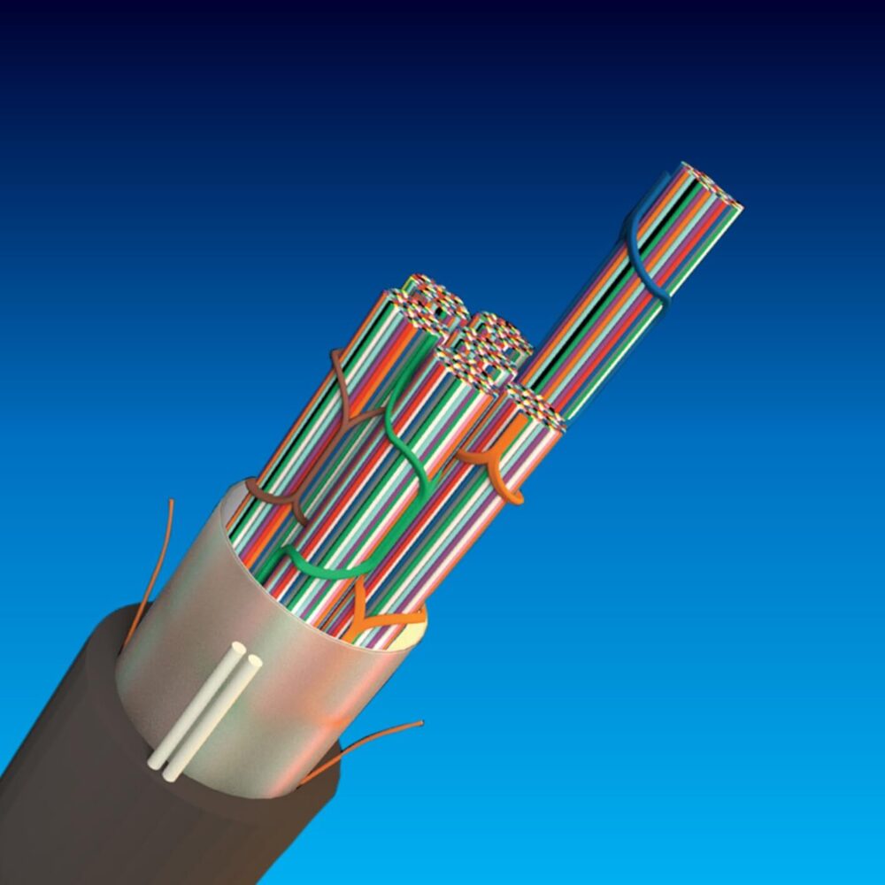
Figure (1) shows the structure of a small-diameter, high-density fiber optic cable. Fujikura‘s fiber optic cable uses Spider Web Ribbon™(SWR™), an intermittently bonded ribbon structure that can be flexibly bundled, and Wrapping Tube Cable™ (WTC™), which is a group of SWR™ bundled and densely packed. The bundled optical fiber unit is wrapped in a wrapping tube and then covered with a sheath on the outside. It also incorporates a tension member to provide tensile strength and a ripcord to open the sheath for cable end preparation for splicing.
Optical Fiber Ribbons
An optical fiber ribbon is made by arranging multiple optical fibers in parallel and bonding them together, creating a ribbon-like structure in which the optical fibers are arranged in a flat plane.
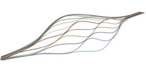
There are conventional ribbons in which the optical fibers are fully bonded together, and Spider Web Ribbons™ in which the optical fibers are bonded intermittently. Figure (1) shows the structure of Spider Web Ribbon™ (SWR™), an intermittent bonding type used by Fujikura. The intermittent bonding type has the following features: 1) it can splice multiple fibers together, 2) Fibers can be easily separated into single optical fibers (no tools required), and 3) it can be easily bundled, allowing for high-density assembly (Figure (2)). Many of the current reduced-diameter, high-density fiber optic cables use the intermittent bonding type ribbons.
Types and Applications of Fiber Optic Cables
Fiber Optic cables are divided into outdoor and indoor use. Some cables also have exterior protection against bird, animal and insect attacks.
The structure of fiber optic cables
Fiber Optic cables can be divided into two types: ① types that use plastic tubes called loose tubes, and ② types that do not use loose tubes. The figure on the right shows a type that does not use loose tubes, which is a small-diameter, high-density type in which the optical fibers are densely packed. It is made by bundling multiple optical fibers called ribbons in which the fibers are aligned in parallel and bonded together. The highest fiber count is 6,912 optical fibers. In high-density cables, the mainstream method of bonding the optical fibers together is the intermittent adhesive type (intermittent bonding type). Fiber optic cables are subjected to a large amount of stress during and after installation. If excessive stress is applied to the optical fibers, there is a risk of fiber break. For this reason, fiber optic cables contain strength members, which are generally made of steel wire. Non-metallic cables use FRP (fiber reinforced plastic) and other materials.
Indoor and outdoor use
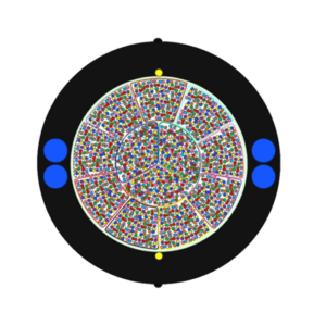
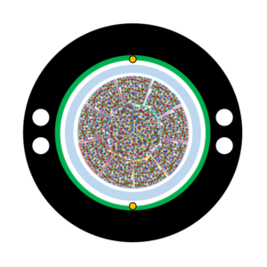
In the figure on the right, (1) is for indoor use, (2) is for outdoor use, and (3) is for outdoor use where rodent protection is required. In general, the sheath for indoor cables is made of flame retardant material, while the sheath for outdoor cables is made of polyethylene. The protrusions on the surface in figure (2) also indicate the position of the tear string.
Non-metallic
Fiber optic cables that DO NOT use any metallic elements in the cables. There is no need to consider grounding or induction issues when laying.
Armored cables
An armored cable is a cable that has an extra protection with a metal tape and a sheath on the outside. It is used along railway tracks and in environments where mechanical strength is required. It also protects the optical fiber from bird and animal damage (woodpeckers, mice, squirrels, etc.). The armor (metal tape) can be easily removed by rip cord that is placed along the length of the cable.
Air-blown cables
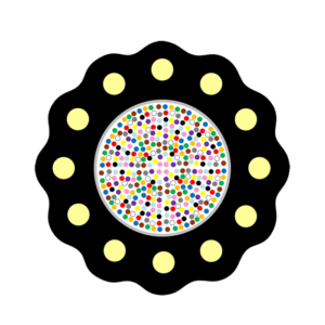
When deploying fiber optic cables into the micro ducts, the construction time can be significantly shortened by using the air-blown method. For this reason, the air-blown cable shown in Figure (4) was developed. The sheath has a special shape to reduce friction with the inner wall of the duct.
Difference between “cable” and “cord”
Sometimes the “cable”, is also referred as “cord“. In general, a cord is a single-core optical fiber covered with a sheath, while a cable is a bundle of multiple optical fiber cores covered with a sheath, and a cable has a more complex structure than a cord. A cord with an optical connector on one or both ends is called a “patch cord”. There is also a “cable” that is a bundle of cords covered with a sheath.
Loose Tube Fiber Optic Cable
A loose tube fiber optic cable is a cable that has optical fibers secured inside a plastic tube, which is called loose tube.
Figure (1) shows the structure of a typical loose tube fiber optic cable. There is a tension member in the center, around which the loose tubes containing the optical fibers are placed, and then a sheath is applied to the outside. Many loose tubes are filled with gel inside, which protects the fibers from the stress and prevents water from entering. While this structure can keep transmission loss low, it has the disadvantage that it is difficult to make smaller diameter cables, because the optical fiber cannot be packed densely. Currently, Non-loose tube, smaller-diameter, high-density cables, that use “intermittently bonded ribbons” having low transmission loss are becoming popular.
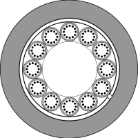
(1)Loose tube cable structure diagram
How to Deploy Fiber Optic Cables
Depending on the deployment area, fiber optic cables can be broadly classified as ① above ground,
② underground, and ③ under the sea.
The most widely used installation method worldwide is to lay a duct (or microduct) underground and deploy the fiber optic cable inside it. There are two methods for deploying an fiber optic cable inside a duct: 1) pulling the fiber optic cable with a wire, and 2) feeding the fiber optic cable using air pressure. In the past, the pulling method was common, but recently the air blowing method is getting popular. The main reasons for this shift are that 1) the air blowing method has the advantages of shorter construction time and 2) it is easy to lay additional fiber optic cable in a duct where an fiber optic cable has already been laid.
Optical Fiber Connection Method
Optical fiber connection methods are divided into two types: 1) non-detachable types that cannot be disconnected once connected, and 2) detachable types.
Non-detachable types include fusion splicing and mechanical splicing. Detachable types are optical connector connections that can be freely inserted and removed. Optical connector connections are further divided into Field Installable Connector and Factory Assembly depending on the manufacturing method.
Fusion splicing
A method in which optical fibers are melted and jointed by arc discharge. Although it requires equipment such as a fusion splicer, the connection loss is very low. The connection loss is highly reliable because it is estimated by a fusion splicer after connection.
[Main places of use] Termination of external lines, domestic permanent links, etc.
Mechanical splice connection
This is a method of connecting optical fibers by physically butting them together inside a protective element. Although the connection loss is high, the connection can be made with simple tools.
[Main use cases] Emergency restoration in station buildings, FTTH connections, etc.
Optical connector connection
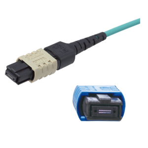
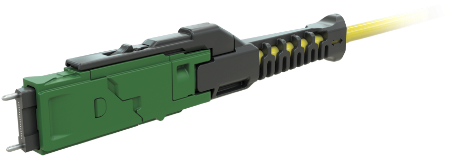
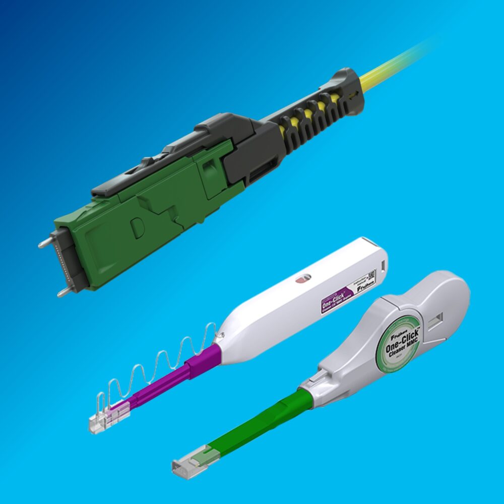
This is a method of connecting optical connectors attached to optical fiber terminals by mating them together. Although the connection loss is somewhat high, the connection can be made without using tools. As a result, construction can be completed in a short time. There are many types of single-core connectors, including SC connectors, LC connectors, MU connectors, and FC connectors. In addition, there is MPO connector as a multi-core connector. Recently, MDC/MMC connectors, that are smaller than the MPO connector, have also been put to practical use.
[Main use cases]
Single-core connectors: Demarcation points, cross-connect points, etc.
Multi-core connectors: Leaf-spine configurations for large-scale clouds, etc.
